 Enlarge drawing ↗
Fin-plate connection
The plate is welded to the column and bolted to the beam web. The beam flanges remain unconnected.

Connect the idealized model to the physical detail. Explore how structural connections and elements look like in reality
These 3D renders are simplified representations for illustration purposes.
A nominal pin transfers forces while allowing relative rotation. These details illustrate shear transfer without relying on significant end-moment resistance.
Enlarge drawing ↗
The plate is welded to the column and bolted to the beam web. The beam flanges remain unconnected.
 Enlarge drawing ↗
A pair of angles connects the beam web to the column. Compare the column bolts with the bolts through the beam web.
 Enlarge drawing ↗
The beam bears on a column corbel. Reinforcement projects from the remote cut ends to reveal the beam bars, column bars and links; beam bars do not continue into the column. The supplementary section shows the bearing and locating dowel.
 Enlarge drawing ↗
Transparent concrete reveals the local beam, corbel and column reinforcement in the simple connection illustration.
 Enlarge drawing ↗
A concealed steel plate slots into the beam and transfers force through transverse fasteners.
 Enlarge drawing ↗
The steel seat supports the secondary beam. Through-bolts pass through both side cheeks and the secondary beam; mounting screws secure the bracket to the supporting beam.
A rigid idealisation maintains the angle between connected members. These moment-transferring details show how flange forces or continuous reinforcement can provide a moment load path. Rigidity must be established for the particular joint and frame.
 Enlarge drawing ↗
Beam flange forces form a couple, while the web transfers shear. Welds connect these load paths to the column.
 Enlarge drawing ↗
The haunch increases the connection depth. The plate, bolts and welds connect the beam and haunch to the column; rigidity requires verification.
 Enlarge drawing ↗
Anchored beam reinforcement and the concrete compression zone provide a moment load path into the column joint.
Real joints can transmit moment while rotating. End-plate details are useful examples for discussing this intermediate behaviour; their actual stiffness classification depends on the plate, bolts, column and connected members.
 Enlarge drawing ↗
The plate finishes at the beam flange levels. Plate bending, bolt deformation and column behaviour contribute to joint rotation.
 Enlarge drawing ↗
The plate extends beyond the beam depth to accommodate additional bolt rows. This detail may be classified as rigid or semi-rigid after assessment.
Follow the force path from the column into the foundation. A physical hinge releases rotation about its pin axis; other bases obtain their rotational restraint from plates, anchors, embedment and the foundation.
 Enlarge drawing ↗
Four anchors are placed between the column flanges. Follow axial force and shear through the column, plate, grout and foundation.
 Enlarge drawing ↗
A central lug sits between two clevis plates. A transverse pin provides a physical rotational release about one axis.
 Enlarge drawing ↗
Chamfered stiffeners connect the column flanges to the base plate. Outer anchor rows provide a lever arm for moment transfer.
 Enlarge drawing ↗
Transparent concrete reveals the embedded I-section, buried base plate and reinforcement cage.
 Enlarge drawing ↗
A steel knife plate is concealed in the timber, with recessed fasteners and a base plate anchored to the concrete.
 Enlarge drawing ↗
The timber post slides into a hollow steel sleeve. Through-bolts connect it to the sleeve, which is welded to the anchored base plate.
Compare the member itself with its end fittings. The end connection transfers axial force; member slenderness and buckling behaviour also determine whether compression can be resisted.
 Enlarge drawing ↗
A hollow steel tube connects to gussets through welded slotted ends. End gussets can be bolted or welded to the framing elements.
 Enlarge drawing ↗
Threaded fittings and pin clevises connect the slender rod to end gussets. Treating it as tension-only neglects its small compression resistance.
 Enlarge drawing ↗
Steel end shoes transfer force from the timber into pins and gussets. Inspect both the timber fasteners and the external pin joint.
 Enlarge drawing ↗
Four bolts at each end secure two full-depth knife plates. The plates contact both faces of the central gusset and connect through a pin.
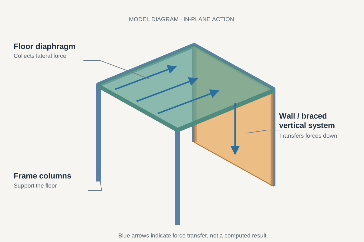
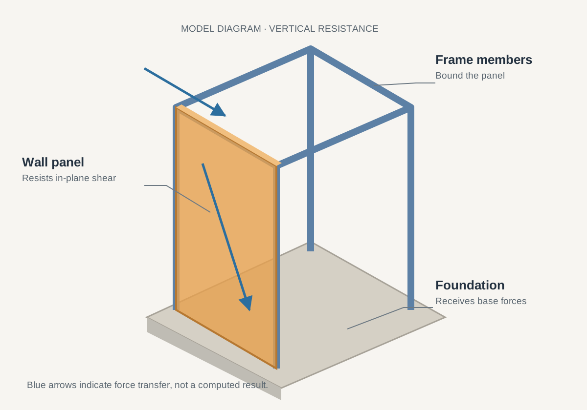
Compare structural floor diaphragms and wall panels, which transfer in-plane forces, with isolated non-structural partitions that divide spaces and are excluded from the lateral stability system.
 Enlarge drawing ↗
A floor diaphragm collects lateral forces and transfers them to vertical resisting systems. Stability Lab represents its in-plane stiffness with equivalent bars.
 Enlarge drawing ↗
A wall panel provides in-plane lateral resistance and transfers forces towards the foundations. Stability Lab uses equivalent in-plane bars rather than a shell model.
 Enlarge drawing ↗
Seven-layer CLT panels bear on steel beams with common top-flange levels. Two rows of through-bolts, one on each side of every beam web, pass through pre-drilled flange holes; top nuts and washers are recessed in CLT counterbores below the floor surface, with securing nuts beneath the steel flanges. Screwed steel surface splines join adjacent panels for in-plane force transfer. Diaphragm stiffness depends on the joints and support connections; details and spacings are schematic. The omitted front strip exposes the flange holes.
 Enlarge drawing ↗
A solid reinforced-concrete slab bears on primary and secondary steel beams with flush top flanges. Headed shear studs are pre-welded directly to every beam to connect the slab and steelwork; there is no profiled steel decking. The cutaway exposes the studs and reinforcement mesh. Temporary formwork is omitted. A rigid diaphragm idealisation assumes adequate in-plane stiffness and connections; details and spacings are schematic.
 Enlarge drawing ↗
Concrete cast over profiled steel decking forms a reinforced floor slab. Headed studs welded through the deck connect the slab to the primary girders and secondary steel beams. The cutaway reveals the studs, mesh and deck profile. This rigid-diaphragm teaching example assumes adequate in-plane stiffness and connections; details and spacings are schematic. Primary girder and secondary beam top flanges share a common plane beneath the decking.
 Enlarge drawing ↗
Corrugated steel roof sheets span between secondary steel beams supported by primary girders. Sheet-to-beam fixings and stitched side laps provide connections for in-plane force transfer. This is a flexible-diaphragm teaching example; actual diaphragm stiffness and resistance depend on the sheeting, laps, fixings and supporting load path. A front strip is omitted to expose the framing. Primary girder and secondary beam top flanges share a common plane beneath the decking.
 Enlarge drawing ↗
Gypsum boards are screwed to light-gauge steel studs located by head and floor tracks. A partial cutaway reveals the framing and optional mineral-wool acoustic insulation. This partition is excluded from the lateral stability system and should not be represented using the structural wall-panel tool.
 Enlarge drawing ↗
Reinforced concrete-block masonry provides in-plane lateral resistance. Selected transparent face shells and grout reveal vertical bars in grouted cells and horizontal reinforcement in bond-beam courses. Reinforcement, spacing and foundation anchorage are schematic.
 Enlarge drawing ↗
A reinforced-concrete wall resists in-plane shear and bending and transfers lateral forces to its foundation. Transparent concrete reveals two reinforcement curtains and confined boundary zones. Reinforcement and anchorage are schematic; Stability Lab represents wall panels using equivalent in-plane bars.
 Enlarge drawing ↗
Red-brick masonry divides the space inside the reinforced-concrete perimeter frame. Head and side separation gaps isolate it from frame movement; the wall is excluded from the lateral stability system. Do not represent this partition using the structural wall-panel tool.
No drawings match this search.


